Glossary
Glossary
Definitions of common OptimalSlope, slope design, and simulation terms used throughout the manual.
Geometry terms
Terms related to imported sections, slope shape, and design geometry.
Cross-section
A 2D representation of the geological model along a selected cutting plane. A cross-section may be imported directly or generated by slicing a 3D model and is the geometry used to define a simulation.
Section layer
A geological or material region within a cross-section. Each section layer can have its own bench and strength properties.
Slicing plane
The XY, XZ, or YZ plane used to intersect selected 3D geometry and generate a cross-section. The live clipping preview shows its current position; the visualiser arrow translates it and the ring rotates a vertical plane.
Azimuth
The horizontal orientation angle of a vertical slicing plane. It allows XZ or YZ cross-sections to be created in different orientations through the model.
Slope anchor
The fixed endpoint used to define the candidate slope geometry. The user can prescribe either the crest or the toe.
Crest point
The upper starting location of the slope profile. In crest-anchor mode, its position and the target slope height define the slope geometry and affect the OSA search region.
Toe
The lower end of the slope profile where the slope meets the lower ground or design boundary. In toe-anchor mode, its horizontal position and elevation are prescribed and slope height is calculated by the software.
Bench
A stepped part of the slope geometry, usually defined by bench height, bench face angle, berm width, and number of benches.
Berm
The horizontal or near-horizontal platform between bench faces.
Slope profile
The 2D line or polyline representing the slope geometry being analysed or optimised.
Slope height
The vertical height of the slope used when defining the section and bench arrangement. It is entered in crest-anchor mode and calculated from the section geometry in toe-anchor mode.
Target slope height
The requested overall vertical height entered in crest-anchor mode. It may be greater than the height achievable using only full benches. See Target and Bench-Compatible Slope Heights for the available height options.
Bench face angle
The inclination of an individual bench face, measured in degrees.
Minimum berm width
The smallest permitted width of the platform between adjacent bench faces.
Bench-compatible slope height
The greatest slope height that accommodates full benches at their specified heights without exceeding the target slope height. It can be lower than the target. Selecting Use target height allows a shorter crest bench to reach the target while the other benches keep their specified height; Use full benches returns to the full-bench arrangement.
Boundary surface
A closed, continuous 3D surface used to trim a section to an excavation, pushback, pit, or other model limit.
Water table (piezometric line)
The groundwater boundary defined for a cross-section. It is represented as a blue polyline in the section visualiser.
Inclination-corrected water pressure
Water pressure calculated with a correction for the phreatic-line gradient: u = γw hw cos² α.
Hydrostatic water pressure
Water pressure calculated without a phreatic-line inclination correction: u = γw hw.
Fault or joint
A geological discontinuity or fracture that may influence rock-mass behaviour and slope stability. Faults are represented in Slope Optimiser as open polylines with assigned strength properties.
Material property terms
Terms used to describe material weight, rock-mass strength, and fault strength.
Unit weight
The weight of material per unit volume, entered in kN/m³. It contributes to the gravitational loading of the slope.
Strength model
A mathematical relationship used to describe how a material resists failure under stress. Slope Optimiser supports the Mohr-Coulomb and Hoek-Brown models for rock layers.
Mohr-Coulomb model
A linear shear-strength model defined primarily by cohesion and friction angle.
Hoek-Brown model
An empirical, non-linear strength criterion for rock masses. Its inputs describe intact-rock strength, rock-mass condition, material characteristics, confinement, and disturbance.
Friction angle (φ)
The angle of shearing resistance, or internal friction, of rock or fault material. It is entered in degrees.
Cohesion (c)
The component of shear strength that is independent of normal stress in the Mohr-Coulomb model. It is entered in kPa.
Intact compressive strength (σci)
The unconfined compressive strength of intact rock, entered in MPa for the Hoek-Brown model.
Geological Strength Index (GSI)
A value representing the geological structure and surface condition of a rock mass for use in the Hoek-Brown model.
Intact-rock constant (mi)
A material constant for intact rock that controls the curvature of the Hoek-Brown strength relationship.
Maximum minor principal stress (σ3 max)
The minor principal stress averaged along the likely slope failure surface. It is entered in MPa for the Hoek-Brown model; the manual specifies -1 when it is unavailable.
Disturbance factor (D)
A Hoek-Brown parameter that accounts for rock-mass strength reduction caused by effects such as blasting and stress relaxation.
Simulation terms
Terms related to simulation inputs, optimisation, and results.
FoS
Factor of Safety. A measure used in slope stability analysis to compare resisting forces against driving forces.
Target FoS
The factor of safety specified as the stability objective for a simulation.
OSA
Overall Slope Angle. In OptimalSlope, Min/Max OSA values define the search range used to explore possible slope profiles.
Minimum and maximum OSA
The lower and upper overall slope-angle limits used to bound the slope geometries considered by the optimiser.
OSA search region
The triangular region shown in the section preview where the optimiser searches for the optimal slope profile.
Optimisation
The process of evaluating candidate slope geometries to identify a profile that meets the defined stability objective and design inputs.
Optimised profile
The slope profile estimated by the optimiser after running the simulation and evaluating candidate geometries.
Failure mechanism
The potential failure path or mechanism considered during slope stability analysis.
Line load
A concentrated section load placed at one selected point on the topography. Its magnitude must be greater than zero.
Distributed load
A load applied over an interval selected on the section topography. It may be uniform, with one magnitude, or linear, with separate left and right magnitudes.
Road input
A section-level input that defines a road by its width and vertical position within the slope geometry.
Maximum fault segment length
The maximum length used when dividing an imported fault polyline into analysis segments. Smaller values give a more detailed representation but require more computation; larger values simplify the fault and can run faster.
Simulation input
The combined section geometry, material properties, bench properties, optional features, and optimisation settings submitted for analysis.
Simulation Check
The pre-submission panel that lists incomplete or invalid section inputs. Its Fix action navigates to and highlights the affected property; Check Again repeats the validation after corrections.
Simulation result
The output from a completed analysis, including the estimated optimal slope profile and associated result data or plots.
Detached plot
A static Output Plot opened in a separate window so that multiple cross-section results can be kept visible and compared side by side.
Data and export terms
Terms related to input files, geometry models, and downstream workflows.
DXF
A drawing exchange format used to import section geometry and stratigraphy into Slope Optimiser and to export slope profiles to other engineering tools.
CBF
The binary file format used to save and reopen an entire Slope Optimiser project.
Stratigraphy
The geological layer model used to define material regions and generate sections.
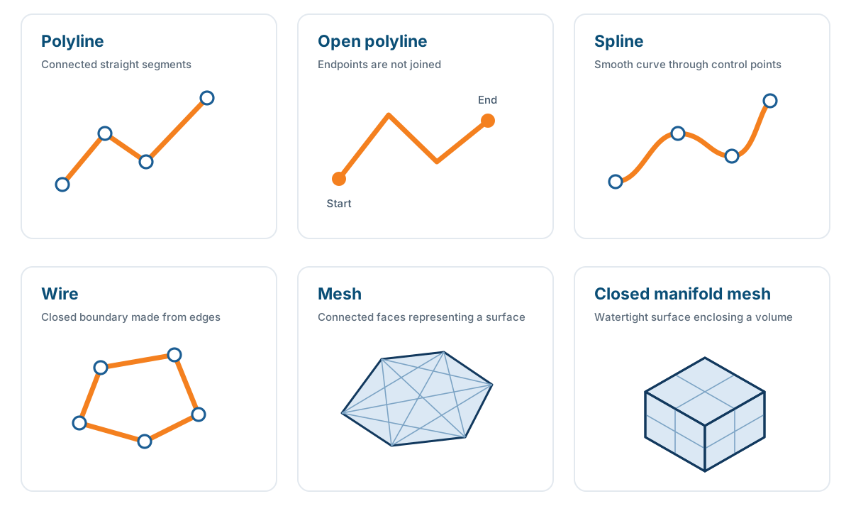
Polyline
An ordered sequence of connected line segments defined by vertices. Polylines are the recommended geometry for water, section, and fault layers.
Open polyline
A polyline whose first and last points are not joined. Faults and joints are imported as open polylines.
Spline
A smooth mathematical curve defined by control points and interpolation. Splines add processing complexity and should not be used for water, section, or fault layers; converting them to polylines can introduce approximation errors.
Wire
A connected sequence of edges used to represent a boundary in section geometry. Gaps, duplicate edges, or incorrect edge ordering can produce an invalid wire.
Mesh
A 3D surface representation formed from connected faces, edges, and vertices.
Closed manifold mesh
A watertight mesh in which every edge is shared by exactly two adjacent faces. Closed manifold geometry helps produce complete and reliable cross-sections.
DXF Polyface
A connected mesh representation in a DXF file. It is the recommended Leapfrog DXF export option because it preserves mesh connectivity and generally requires less post-processing.
DXF 3D Face
An individual face entity in a DXF file. A model exported as separate 3D Faces requires additional processing because the faces are not stored as one connected mesh.
Block model
A 3D grid of blocks used to represent material, geometry, or simulation result attributes such as slope angle.
JSON simulation export
A text-based export containing the properties and inputs associated with an individual section and its layers.
Local XY export
A DXF export option where the section is flattened onto the XY plane. This is useful for general workflows that require 2D geometry.
Rocscience export
A DXF export option that prepares 2D section geometry for Rocscience software and automatically generates the closed external boundary required by the model.
ADDMOD
A Datamine function used to combine model data, for example adding OptimalSlope slope-angle output to an existing block model.
results matching ""
No results matching ""
Try a shorter phrase or one of the suggested searches above.